Cause Analysis:
Usually, the lens of the welding gun is damaged, including but not limited to protective mirror, focusing, collimation, and reflection. Any one or more of these damages can cause this to occur
First replace the protective lens and look at the focus, then check the reflection and collimation, and replace the damaged lens.
In addition, check whether the laser fiber head part is dirty or damaged
Troubleshooting:
Replace the damaged lens, please check the replacement plan in the structural installation
2.The motor is overheating and cannot be soldered
Performance:
The motor overheats on the home page and cannot be soldered
Cause Analysis:
Thermal is not plugged in or damaged
Troubleshooting (one of the two options can be selected):
1. Replace with a new thermal
2. Directly shield this alarm in the settings, set it to 0
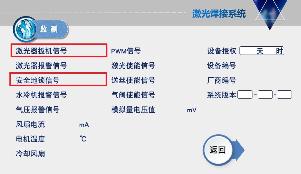
3.When the welding gun is in contact with the workpiece, the detection page [Safety Lock Signal] is displayed in gray
Performance:
When the welding gun is in contact with the workpiece, the detection page [Safety Lock Signal] is displayed in gray
Cause Analysis:
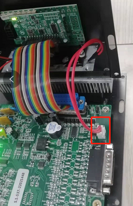
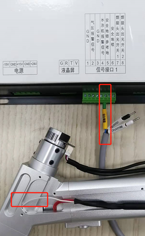
When the welding gun is in contact with the workpiece, the 5/6 pins of the signal interface 1 should be in a conductive state. When there is an open circuit or an internal problem on the main board, it will be displayed in gray. The structure is as shown below.
logic
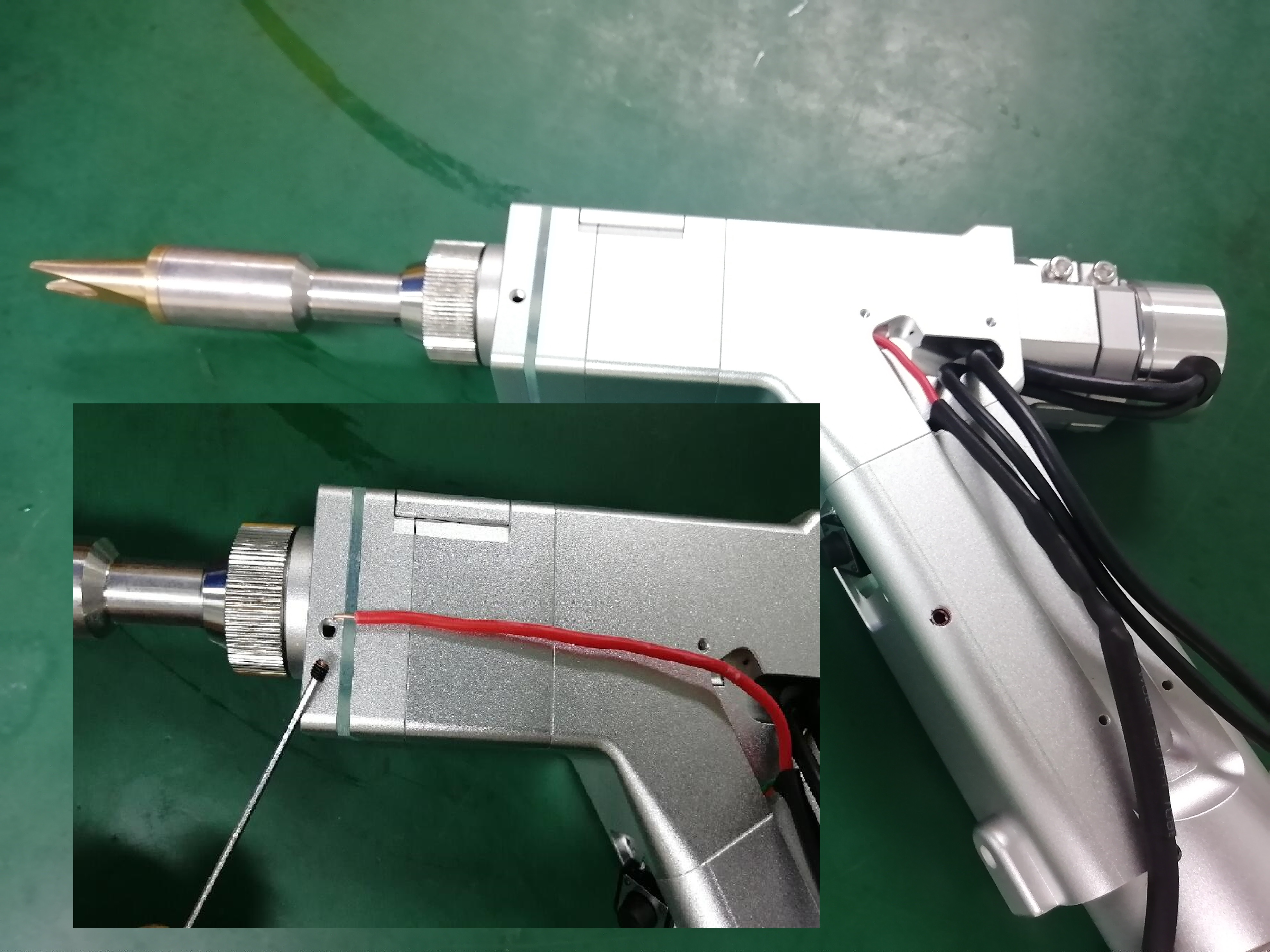
The 5 feet are connected to the safety lock chuck, which is in contact with the workpiece
The 6-pin is connected to the welding torch head through a three-core wire
Troubleshooting:
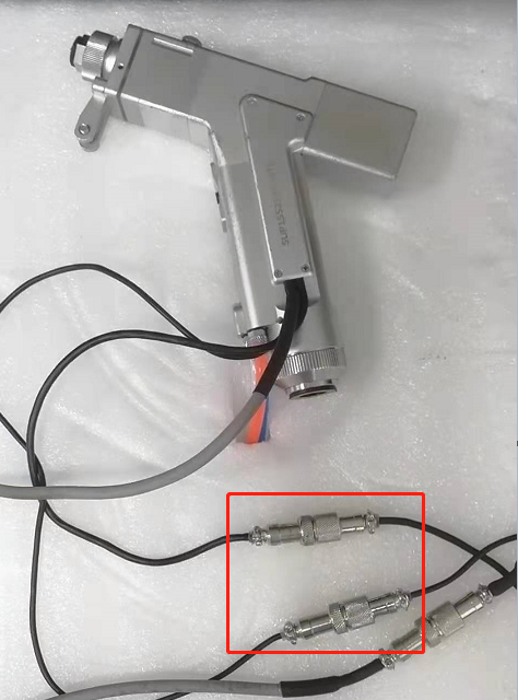
①At the same time, test whether the trigger signal is normal. In some cases, the aviation socket is loose, which will result in no two signals. The aviation socket is located 80cm behind the wire of the welding gun.
② Directly short-circuit the 5/6 pins of signal interface 1. If it is connected, the main board is fine, and continue to the next step.
③Measure the on-off of the safety lock clip to 5 feet
③ Measure the on-off between the copper nozzle and 6 feet. In some cases, the line is broken. You can use a multimeter to measure the on-off of the signal.
4.When the trigger button is pulled, the detection page [Laser Trigger Signal] is displayed in gray
Performance:
When the trigger button is pulled, the detection page [Laser Trigger Signal] is displayed in gray
Cause Analysis:
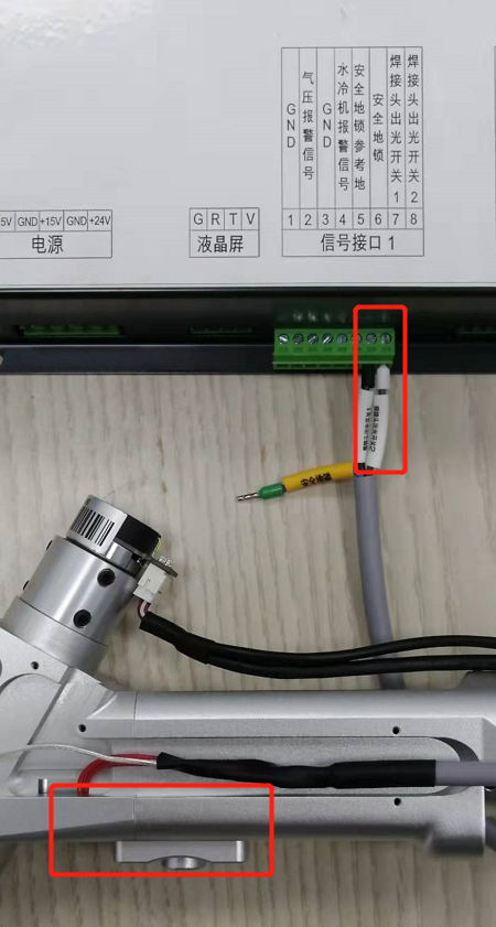
When the trigger is pulled, the 7/8 pins of the signal interface 1 should be in a conductive state. When there is an open circuit or an internal problem on the main board, it will be displayed in gray. The structure is as shown below.
Troubleshooting:
①At the same time, test whether the safety lock signal is normal. In some cases, the aviation socket is loose, which will result in no two signals. The aviation socket is located 80cm behind the wire of the welding gun.
② Directly short-circuit the 7/8 pins of signal interface 1. If it is turned on, there is no problem with the main board. Continue to the next inspection.
③ Disassemble the button and measure the continuity between the button and the terminal. In some cases, the line is broken.
④ When there are no problems with the above, most of them are the problems of the button itself, such as poor contact, etc., the button needs to be replaced
5.In the welding state, after pulling the trigger, the air is sent out and the wire is fed, and the red light is visible normally, but no laser light is emitted.
In the welding state, after pulling the trigger, the air is sent to the wire, and the red light is normally visible, but the laser cannot be emitted
Logically, the signal emitting the laser is also emitted when the air is out, when the laser does not receive the light signal (port failure) or when the laser has a problem
(1) First exclude the presence of an alarm in the laser itself
(2) Where it involves normal after shutdown and restart, most of them may be resettable alarms of the laser itself, it is recommended to contact the laser manufacturer or monitor the internal alarm
(3) For whether the laser has received a trigger signal, two schemes to test
The simplest thing is to link the laser's monitoring software to see which signal is missing. In addition, the signal port of the signal interface three can be measured Typically, the laser emits light only when it receives an enable/PWM/analog signal, so we can measure whether the signal is emitted in the operating state
(Be sure to measure each port of the signal interface three when the air is out of the welded state)
Enable signal: 2/4 pin output 24V voltage
PWM modulation demodulation signal: 6/7 pin Output voltage 24V
Analog signal: 4/5 pin equal proportional voltage, 10V at full power
If the above signal is normal and still does not emit light, contact the laser manufacturer to deal with it
If one of the enable/PWM has no voltage, it can be used together, such as PWM connecting the enable signal pin
If there is no voltage in the analog quantity and the red light is a line, return to the factory to repair or replace the motherboard
If there is no voltage in the analog, and the red light is a point, check whether the 15V switching power supply ± is reversed
6.In a short period of time, the protective mirror is damaged and there are burning spots, and the light-emitting surface of the protective mirror is dotted with damaged spots, showing black or white black spots.
Performance:
In a short period of time, the protective mirror is damaged and there are burning spots, and the light-emitting surface of the protective mirror is dotted with damaged spots, showing black or white black spots.
Cause Analysis:
Due to the influence of process/method/setting, etc., the anti-slag will cause damage, and very few are abnormal laser light output.
solution:
① Appropriately increase the air pressure. Usually, the flow rate is not less than 15, and the pressure is not less than 4. It is recommended to use an oxygen pressure gauge of not less than 2 kg.
②When welding, try to weld the welding gun and the plate at 45°, not vertical
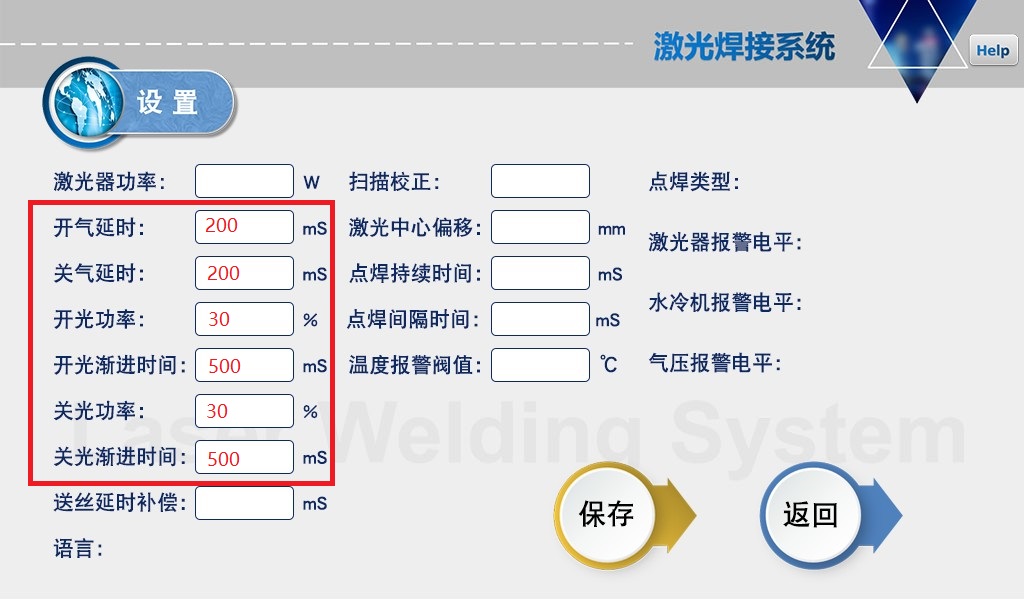
③The setting parameters should be slowly increased and decreased as much as possible. For example, the delay of on/off gas is 200-500ms, the optical power of on/off is 20%, and the gradual time of on/off is 200-300ms. As shown in the figure, 0 cannot be set.

④When welding aluminum and galvanized sheet, this material will damage the lens more easily than other materials, so the minimum power should be used for welding.
⑤The quality of the protective mirror also determines the durability of its use. It is recommended to use the original lens
⑥At high power, compared with low power, the loss of the lens will increase, which is an uncontrollable range
⑦ When the above can not be dealt with, you can replace the F200 focusing lens + lengthened and wide scale tube to reduce splashes (additional purchase is required)
7.In the welding state, the output is intermittent, and the wire feed/air is intermittent
Performance:
In the welding state, the output is intermittent, and the wire feed/air is intermittent
Cause Analysis:
Trigger button signal or safety lock signal lost
solution:
According to its operation logic, only when the [Laser Trigger Signal] and [Safety Lock Signal] are valid, the light will be emitted (the laser state is normal), and there is no alarm on the home page.
When the light is intermittent, check the above two signals through the monitoring page, which will disappear. For the disappeared signal, do the next monitoring.
If both signals are present
①Safety lock signal disappears
Clamp the safety lock clip directly on the scale tube to see if it is normal. If it is normal, it may be the cause of the plate. Some plates such as rust or oil will cause poor contact.
②The trigger button signal disappears
Try pressing the trigger button hard, if the signal flashes, there may be a bad trigger button contact, replace the trigger button (new and old models are not common)
③ Unable to detect signal loss
Because the refresh frequency of the detection page is much lower than the sampling interval of the chip, it returns to normal after an instantaneous disconnection, and the detection page cannot be seen in this case.
In view of this situation, short-circuit the 5/6 pins of the signal interface 1 to make the safety lock take effect, and then solder it normally to see if it will appear.
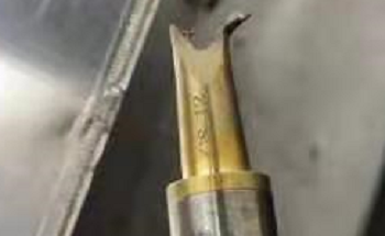
8.copper burner
Cause Analysis:
During the welding process, heat diffuses to the copper nozzle and causes damage. The processing process should first analyze the heat source, lens astigmatism, red light polarization or external material heat conduction.
solution:
Make sure before handling
①The red light is centered (polarized light will cause the light to hit the mouthpiece)
②Appropriate scan width (usually within 5, usually set to 3)
③The focus is 0 focal point (the scale tube can be set to 0)
1. First, emit light to the ground from a long distance, and check whether the copper nozzle is hot. If it is not hot, it means that the lens has no problem and there is no astigmatism. If it is hot, the damaged lens needs to be replaced.
2. If the welding is hot under the above normal conditions, it means that the material conducts heat during welding. In actual use, the outer corner copper nozzle is more likely to be damaged than the inner corner, and red copper copper nozzles can be used.
3. The welding method also affects the heat, try to weld the welding head and the material at 45°∠ welding
4. Highly reflective materials such as aluminum plates will also cause the copper nozzle to become hot, which is uncontrollable
9.After the power is turned on, the motor at the rear of the welding head whistles / the swinging red light is abnormal / overheating / the swing width cannot be adjusted
Problem phenomenon:
After the power is turned on, the motor at the rear of the welding head whistles / the swinging red light is abnormal / overheating / the swing width cannot be adjusted
Problem cause and solution:
The driver in the control box controls the motor to swing. When there is a signal error or the driver does not match the motor, the above problems may occur.
We should first check whether the wiring is normal, and then deal with the abnormal noise by adjusting the motor drive, as follows
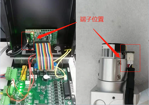
①The terminal of the connecting wire between the driver and the motor is in poor contact (SUP20S model)
In the welding gun of SUP20S, the connection terminal is built-in. Poor contact may cause abnormal signal and cause howling. Try to unplug and plug again.
②There is an open circuit in the five-core aviation plug of the connecting line between the driver and the motor (SUP15S model)
On the welding gun of SUP15S, the motor signal and power supply are connected through the air plug interface (two black wires). The air plug interface should be disassembled to check whether the welding pins of the car are broken or soldered
③ Prerequisite: If the swing is normal, there is no red light flashing, and the wiring is confirmed to be OK, it means that the driver and the motor do not match or interfere
This occurs on newly installed equipment or equipment with a tip replacement and can be improved by adjusting the driven potentiometer.
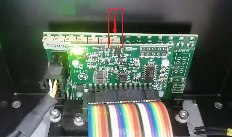
Potentiometer position: Y-axis (left side of the picture below) from left to right above the plug, the seventh position
Adjustment method: Use a flat-blade screwdriver to screw in one direction under the power-on state. If there is no response after more than 10 turns, screw it back to reset, and then continue to screw in the other direction.
(If adjusting the seventh potentiometer has no response, then adjust the fourth one from left to right)
10.Motor does not swing
The normal light spot becomes a light spot line by swinging the motor (left), if the motor does not swing, then a dot will be displayed (right)
1. Whether the software part is set correctly
2. Hardware part inspection
1. The power supply of the swing motor is 15V power supply, we should first measure whether the power supply of the 15V switching power supply is normal.
2. In addition, the 15V switching power supply is divided into positive and negative, and the wrong wiring will also cause the motor to not work. V1 is connected to 15V+, V2 is connected to 15V-, and any COM on the 15V switching power supply is connected to pin 2 GND!
3. (Model SUP20S) Check whether the interfaces on both ends are inserted in place
4. (Model SUP15S) If the power supply is normal, it is usually caused by an open circuit. The control box and the motor are powered by a 2-core wire. Focus on checking the air plug of the 2-core wire, and disassemble it to see if the circuit is open.
5. (Model SUP15S) When there is no problem with the 2-core cable, check the signal plug of the 5-core cable, and also disassemble it to see if there is an open circuit
6. Check whether the rainbow link cable between the motherboard and the driver is loose