ZMC408SCAN is a new open laser vibroscope motion controller supporting EtherCAT bus, designed for industrial laser+vibroscope+motion control applications. It supports complex continuous trajectory control requirements for 16 motion axes, and can realize mixed interpolation of vibroscope axis + pulse axis + bus axis.
1.ZMC408SCAN to achieve laser processing contains two major parts of motion control and laser control, only one ZMC408SCAN controller can realize the vibration mirror control + laser energy control + motion axis control.
(1) Motion control: using common motor drive devices (pulse type or EtherCAT bus type drives are supported), or through the laser oscillator to achieve motion.
(2) Laser control: connect many types of lasers commonly used in the market through LASER, OUT output port supporting PWM function or EXIO expansion interface. The MOVE_OP instruction controls the laser switch, the MOVE_PWM instruction adjusts the frequency and duty cycle of the laser, and the MOVE_DELAY and MOVEOP_DELAY instructions control the delay of the switch light.
2. Advantages of ZMC408SCAN in the field of laser processing.
(1) The ZMC408SCAN has a built-in high-precision PSO position synchronization output function, which enables control of the laser output pitch to remain constant in high-speed processing even after deceleration adjustment when processing rounded corners and curved parts.
(2) Support laser oscillator control and oscillator feedback, including 2 oscillator interfaces, supporting 2D oscillator and 3D oscillator, with the motion command MOVESCAN without acceleration and deceleration, the oscillator processing at the corners is automatically delayed to complete accurate and efficient laser control and improve the productivity of laser processing equipment.
(3) Flexible adjustment of laser on/off delay time in motion through the command, fast response, accurate to us level control, and simple setup process, greatly reducing the engineer's tuning time.
(4) comes with LASER laser control interface, supporting support for IPG, YLR, YLS and other types of laser power, but also with an EXIO expansion IO interface, through a custom adapter board, flexible control of a variety of mainstream lasers on the market.
(5) support PC control of 16 ZMC408SCAN controller working simultaneously to form a kind of vibrating mirror array of laser processing.
(6) On-board 4-way high-speed differential pulse output with 4-way high-speed differential encoder feedback, support for EtherCAT bus driver control, support for 5-axis XYZAC axis interpolation, support for mixed interpolation of the vibroscope axis and motion axis.
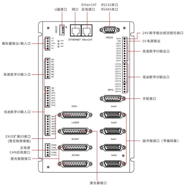
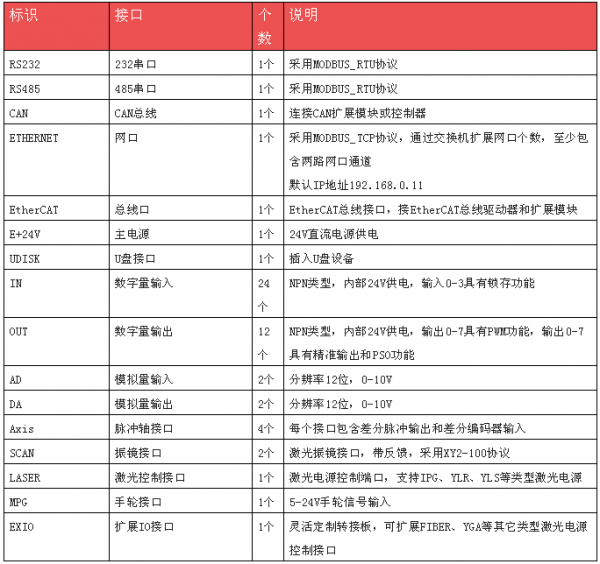
Interface description.
1. The interface of the controller is described in the following table.
2. ZMC408SCAN controller LASER laser power interface features.
(1) LASER laser power interface supports the connection of IPG, YLR, YLS and other types of laser power.
(2) The laser, red, enable and other output signals can be sent directly through the controller's commands to operate the laser and allow the laser to produce a response.
(3) DB interface with 1 PWM output port.
(4) can receive the laser signal, can display the IN signal and make the corresponding response.
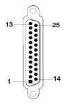
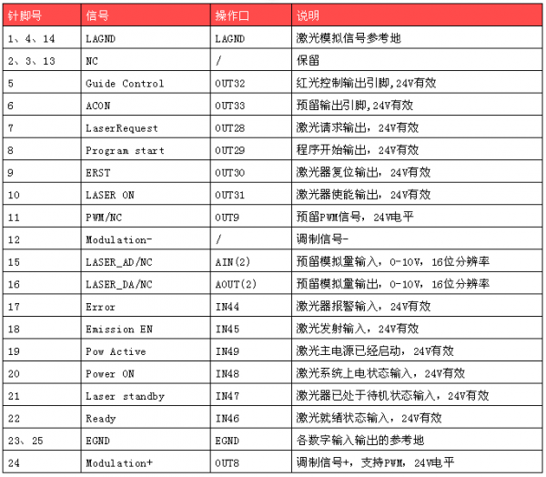
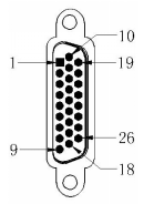
3.LASER laser power interface with DB25 pin male, pin description see the following table.
Attention.
(1) The inputs and outputs in the above table support customization of other signal roles except PWM and Modulation.
(2) OUT(9), AOUT(2) and AIN(2) are reserved signals, which are not available in the standard model, please select special model when ordering if needed.
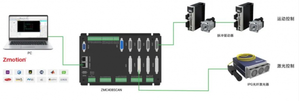
03、Control system wiring reference
1. Take ZMC408SCAN control FIBER laser as an example, divided into two parts: motion control and laser control. The reference architecture is shown below.
→The motion control part adopts pulse-type driver, and uses its own AXIS differential pulse input interface to connect the pulse-type driver.
→Laser control part uses LASER interface to connect to the laser, and completes the wiring of the control circuit according to the laser manual, adjusts the laser energy through the DA analog output port, and controls the laser switch through the Modulation modulation signal port.
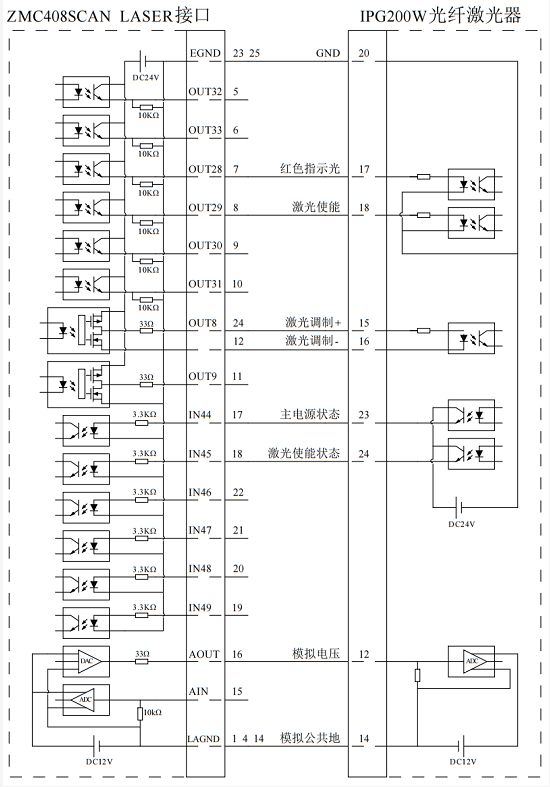
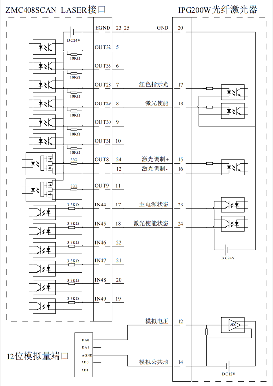
2. Controller and laser wiring reference
The internal circuit diagram of LASER laser power interface and the wiring reference with IPG200W fiber laser are shown in the following figure.
(1) Using the 16-bit DA wiring reference inside the LASER interface (supported by special models)
(2) Use the 12-bit DA wiring reference on the external port of the controller
(3) LASER laser interface wiring principle as shown in the figure above, digital IO interface except OUT8, OUT9 can be defined.
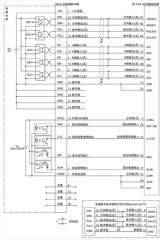
Reference example of differential wiring with Panasonic A5/A6 Servo Drive.
Differential pulse axis interface wiring principle as shown in the above diagram, there are differences in the wiring methods of different driver models, please connect with caution.
Please use shielded twisted pair wiring, especially in harsh environments, be sure to make the shield fully grounded.
04、Fiber laser control example
1. Operation steps
(1) Please follow the above wiring instructions for correct wiring.
(2) After power on, please choose any one of the three interfaces, EtherNET, RS232 (default parameters can be directly connected), RS485 (default parameters can be directly connected, hardware needs to use adapters) to connect to ZDevelop.
(3) Monitor the corresponding IO points through the input/output window in the ZDevelop view bar.
(4) Monitor and control the corresponding analog input and output ports through the AD/DA window in the ZDevelop view bar; (5) Monitor and control the corresponding analog input and output ports through the ZDevelop view bar.
(5) Send commands PWM_FREQ(PWM No.) = frequency and PWM_DUTY(PWM No.) = duty cycle via ZDevelop online command.
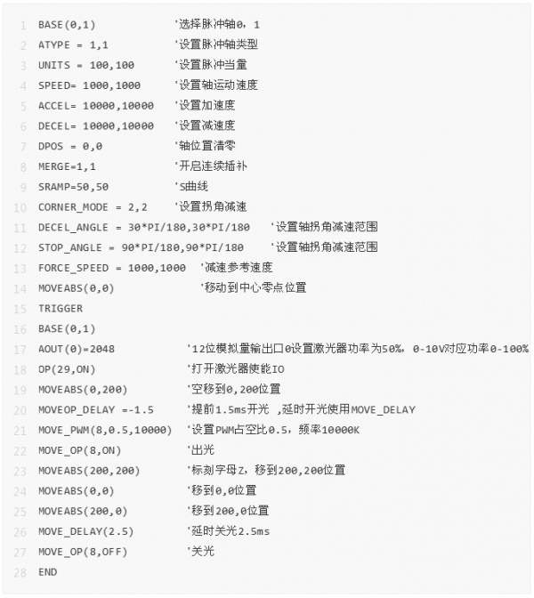
2. Reference BASIC routines: Laser control reference to the previous section pin description
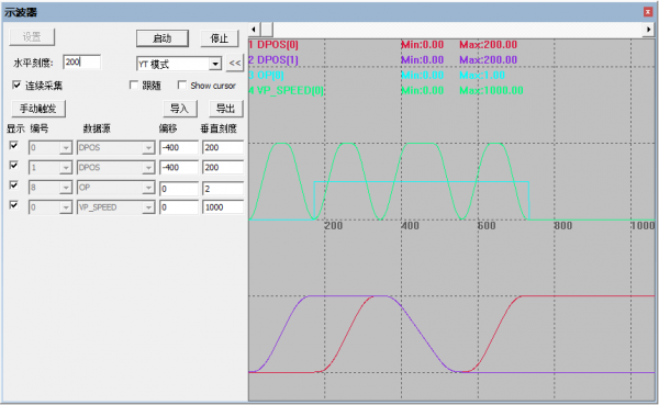
The oscilloscope samples the motion waveform as follows: 1.5ms light on in advance of the motion to the position (0,200), marked with the letter Z, and 2.5ms light off at the end of the motion delay.
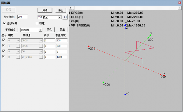
The 3D mode makes it easy to see which segment of the motion laser is on.